Building a IoT farming from Swinburne workshop
Hello there. Recently, I joined a Swinburne workshop about IoT and get a farming kit from them. So, I will share my experience of assembling this kit.
Assembling the circuit
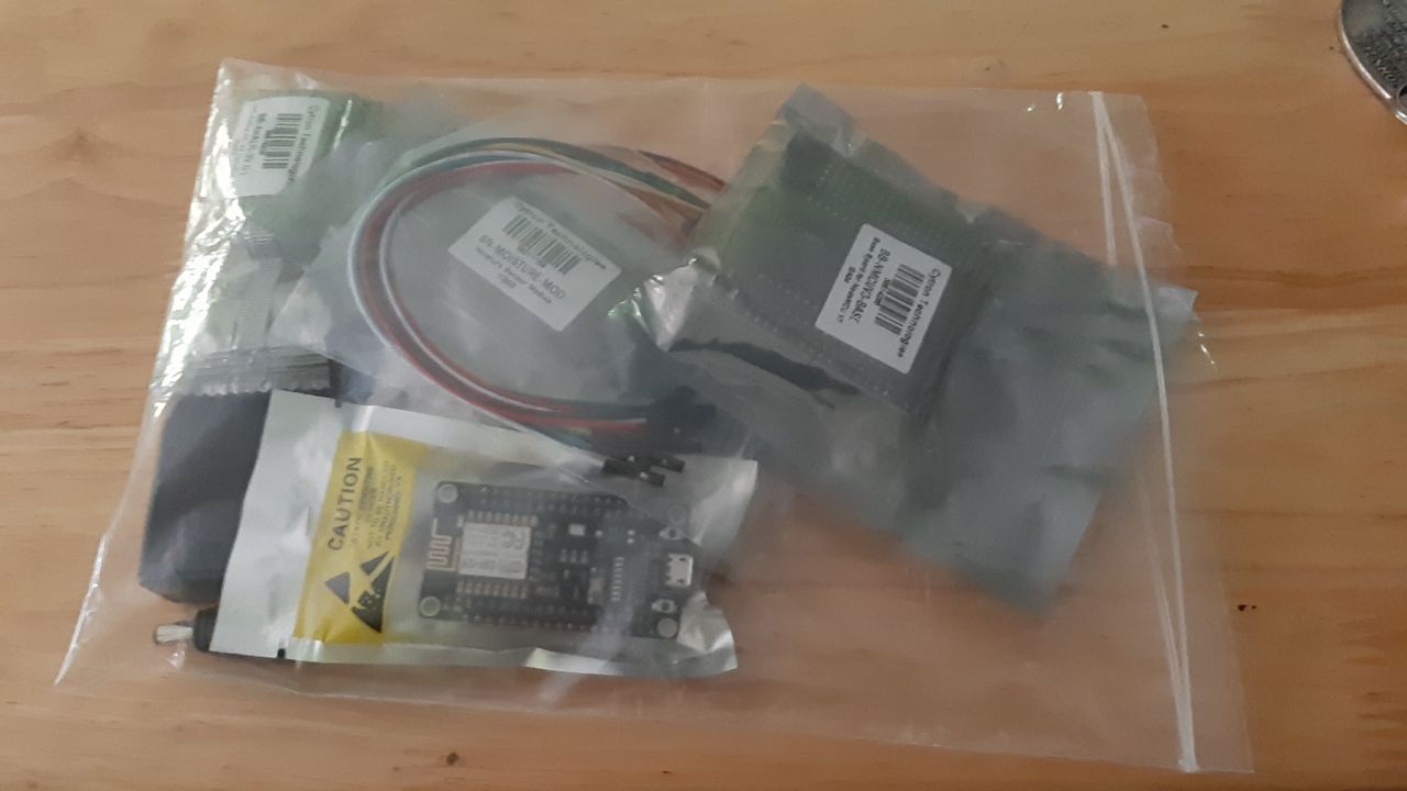
At first, I received a package of electronic component and started to connect the main board to battery. Unfortunately, the wire of battery holder is broken and the main board cannot turn on.
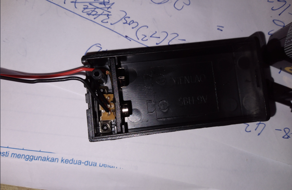
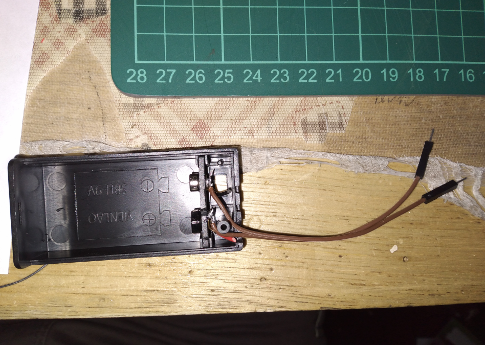
After measuring both wire using multimeter, I noticed that somewhere in the middle of red wire is broken. To fix this, I just cut off the wire and replace it using a jumper wire from the farming kit. After the soldering iron is hot enough, the new wire is soldered in place.
Writing boilerplate code and preparing server
Based on the workshop, I should use Arduino IDE with ESP plugin to program the main board which is a nodeMCU with esp-12e core. But, the Arduino IDE for Linux is come in appimage format and I don’t want to pollute my precious EXT4 file system with appimage. So, I use PlatformIO instead. By setting the board to esp-12e in platformIO config file and write a Hello World c++ code, everything is good to go.
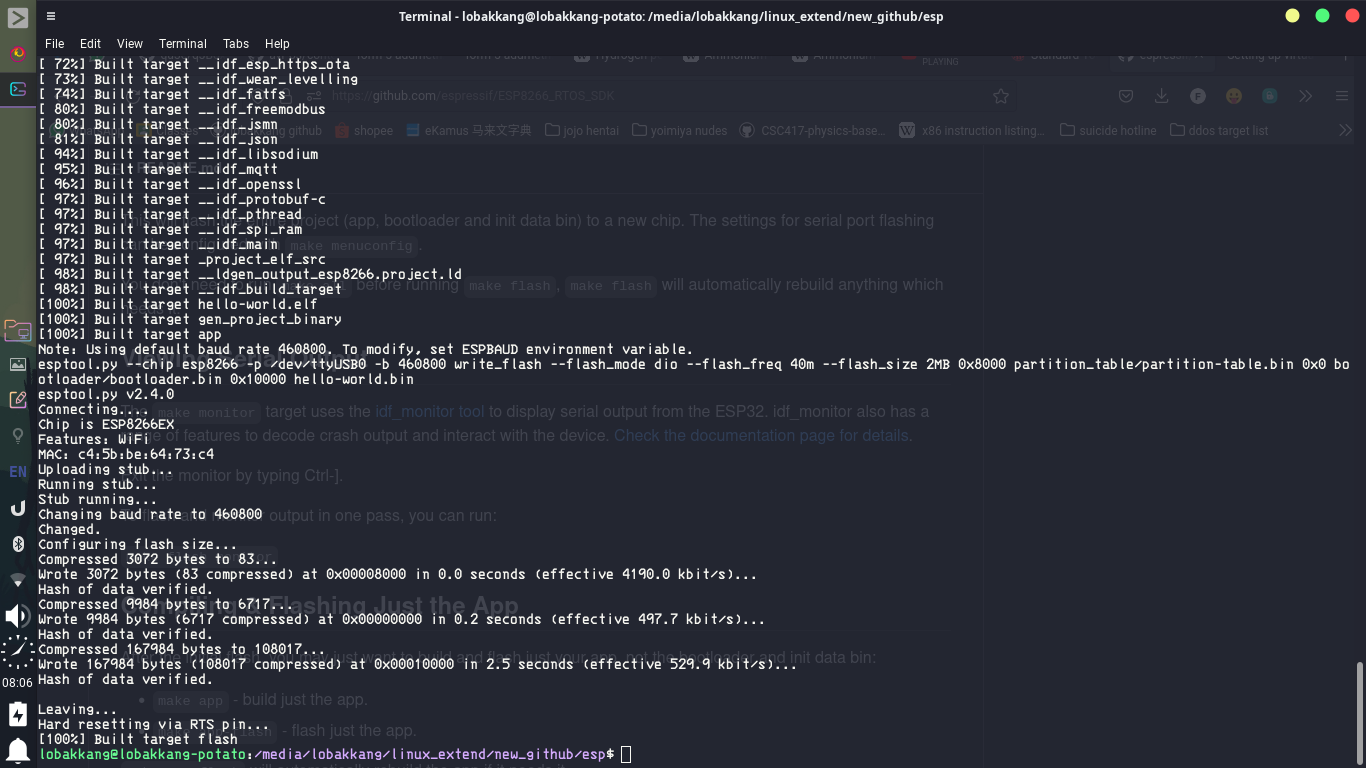
After, making a working program run successfully on the nodeMCU, it’s time to prepare the server side thing. The platform I am going to run the MQTT server and node red server is a TV box installed with armbian instead of my laptop. The reason is I want to make the IoT farming robot run 24 hrs and really use it in real life. So, running a server on my laptop is not a good idea.
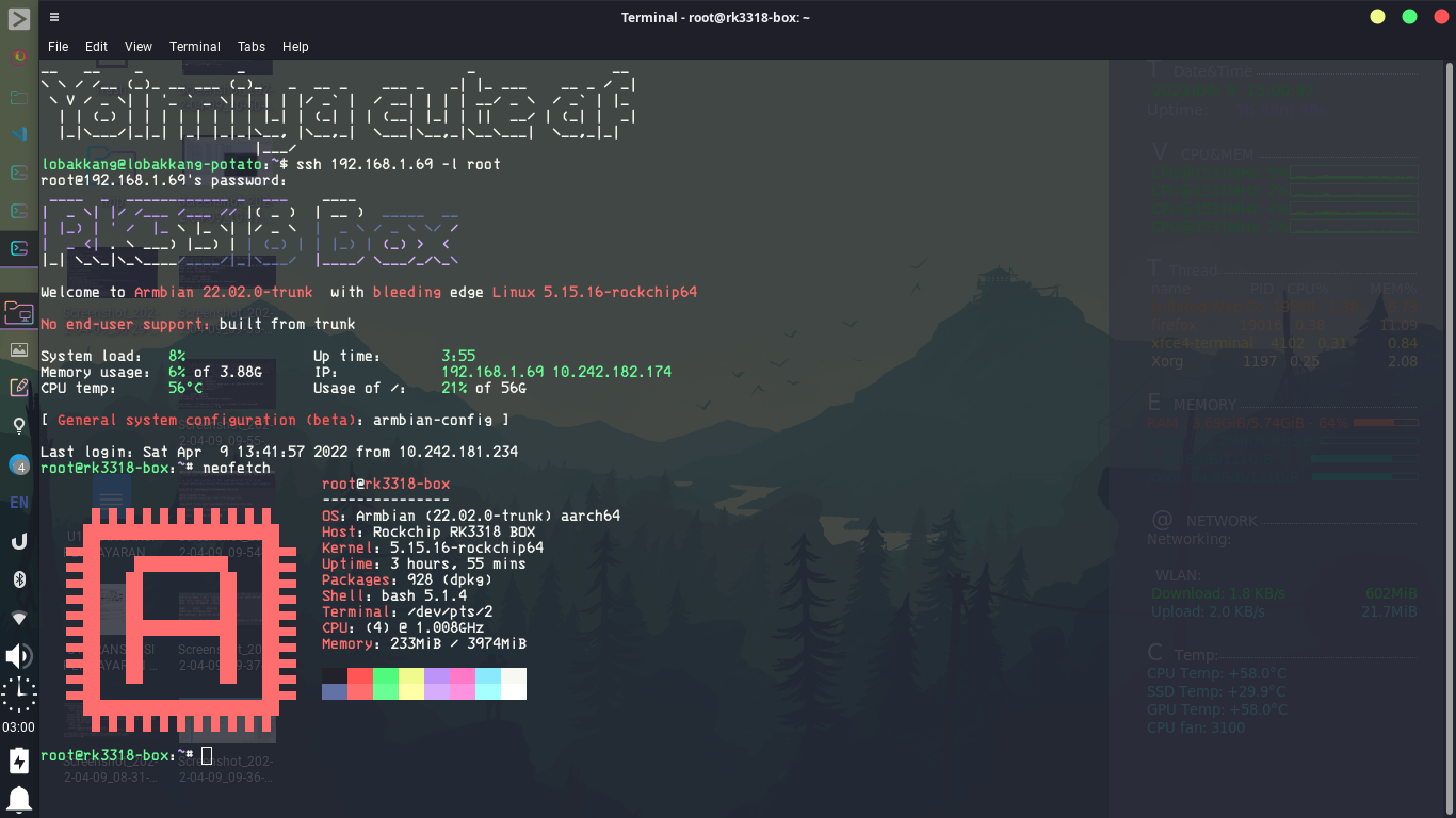
Luckily, the MQTT broker server I am going to use, mosquitto is available in armbian repository. Meanwhile, the Node Red can be installed from npm repository. After installing all the thing I need, I started to configure the mosquitto. Due to the IoT farm is going to use in real life, everything need to be secure and practical. So, I added auth username and password to the config.
However, due to my home weird networking, the server is actually unreachable to nodeMCU. This is because they are separated by two router in two different LAN.
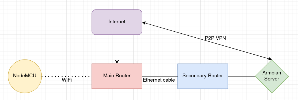
To establish the connection, there are two way. First, is by using P2P VPN, zerotier to something like a virtual LAN but installing a VPN client on a tiny ESP is not practical. So, I am going to use another way, port forwarding. Basically, I port forward the MQTT port of the server, 1883 to a port of the secondary router, 6969.
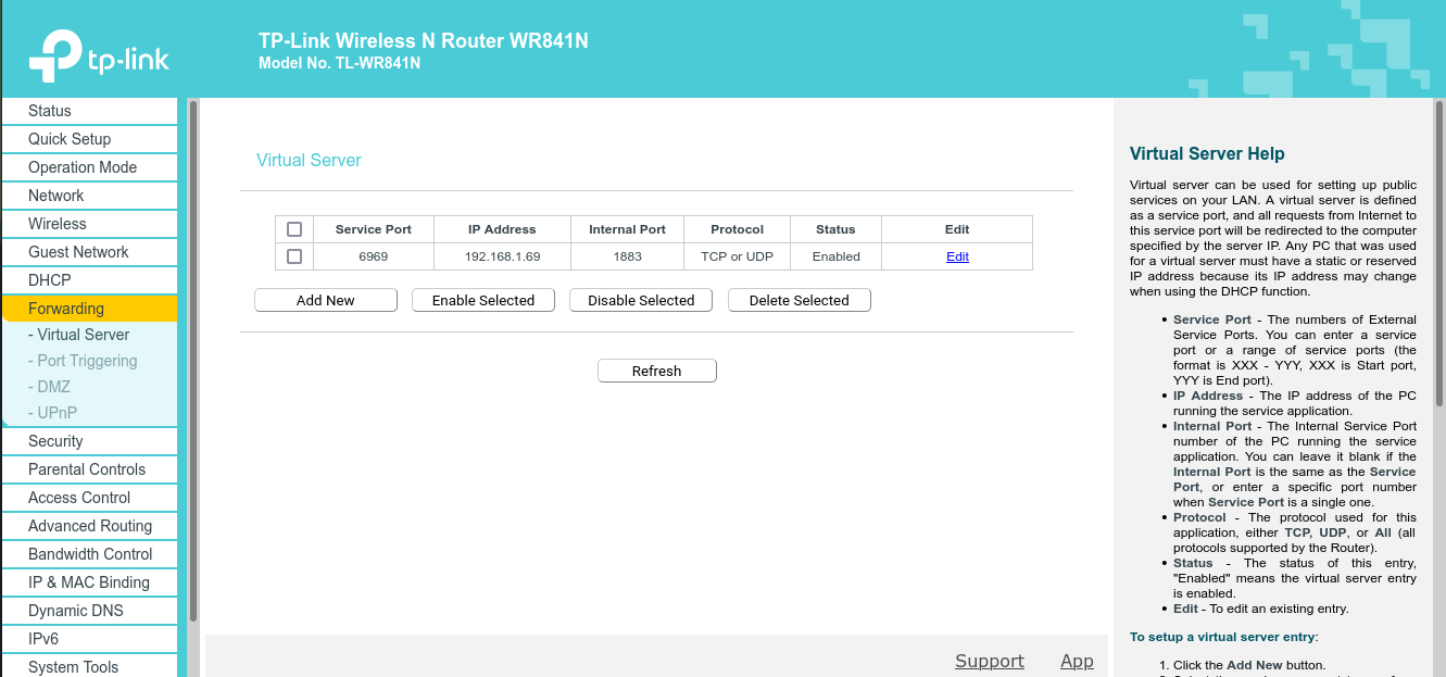
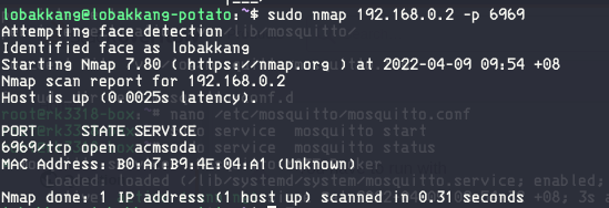
Then, to ensure the port is really working, I scan the port from the primary router using nmap.
Coding for NodeMCU
Now, the server preparation is done. It’s time to write some code for NodeMCU. Unfortunately, I delay this for too long until the example code for IoT farming in WhatsApp is not available. So, I have to write everything on my own. After, a few hours of writing and search endless of Stack Overflow, I finally make a prototype code. When I upload it onto the NodeMCU, I was full of disappointment because it is not working. No matter how I change the coding logic, the code is still not working.
As a senior programmer of SMK Jalan Arang robotics club, I smell something sus in the networking. I scanned the LAN traffic using wireshark with MITM sniffing and realize there are no out going packet from NodeMCU but the ping is still working.

I discussed with another robotic club senior, Declan and he suggest me to use datatype IPAddress to define server address:
1 | |
instead of write it in URL:
1 | |
After that, the code is finally working. (In the screenshot, I test it using a MQTT server installed on my laptop)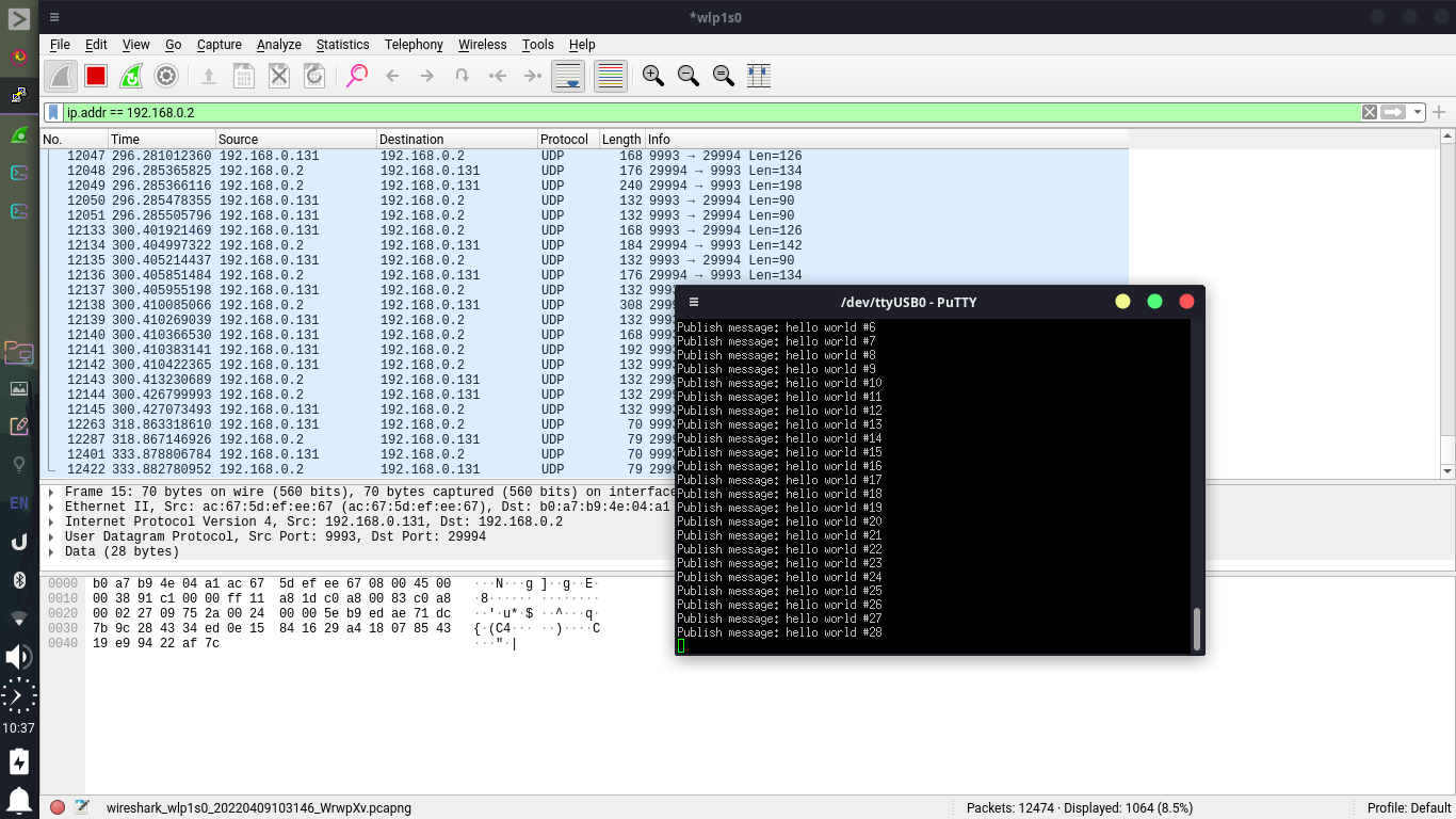
Node Red Server
Now, coding for NodeMCU is done. It’s time to code the Node Red Server. Since Node Red use drag and drop to do coding, this step is far easier than previous steps.
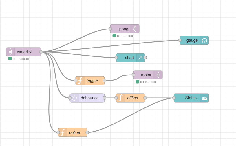
Then, here’s the ui. To access the web page, P2P VPN is required to connect.
phone

PC
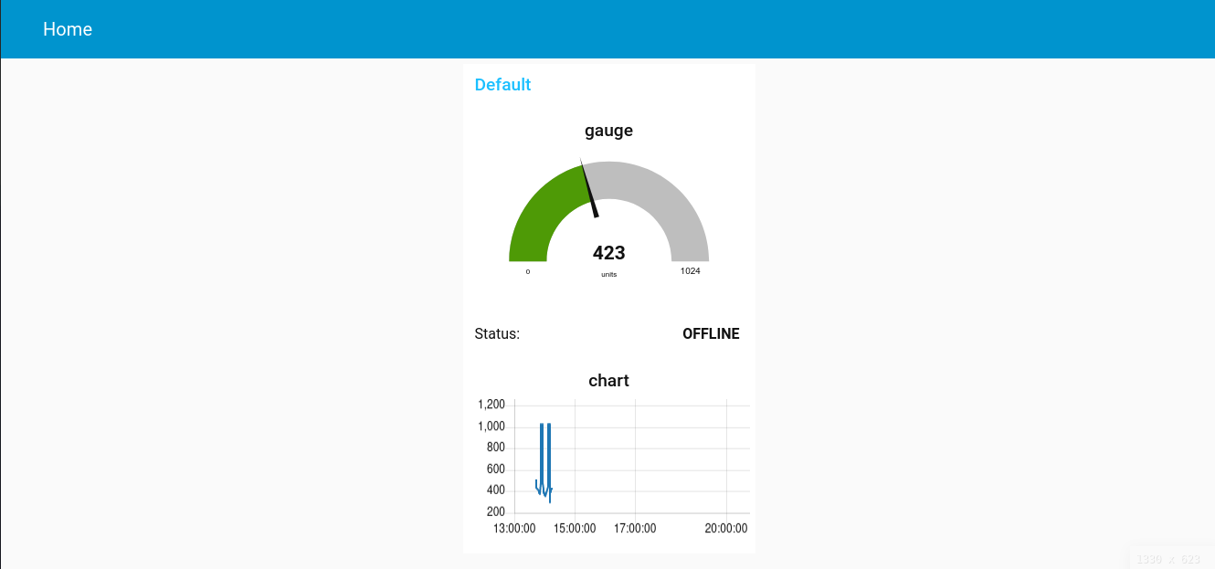
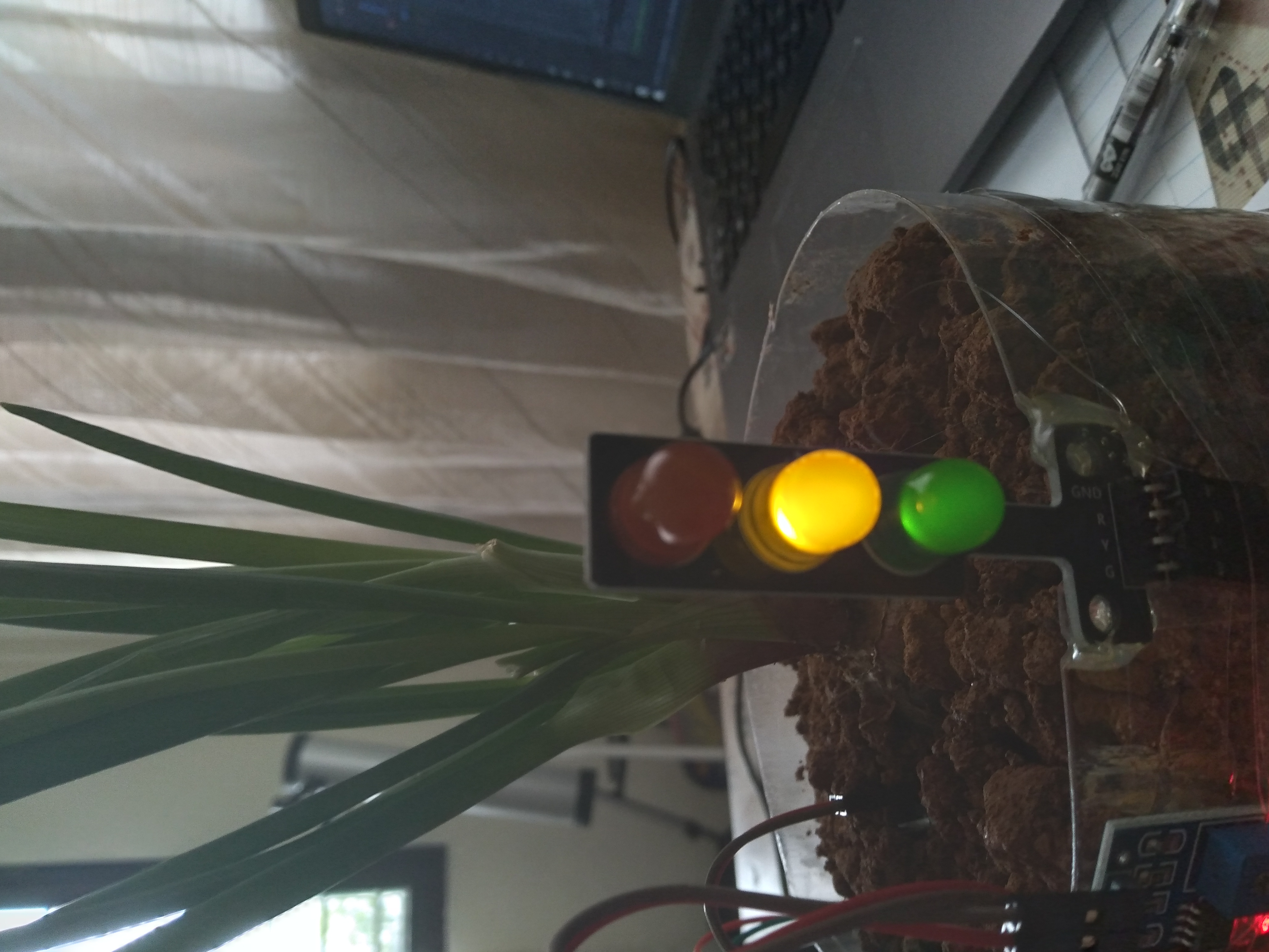
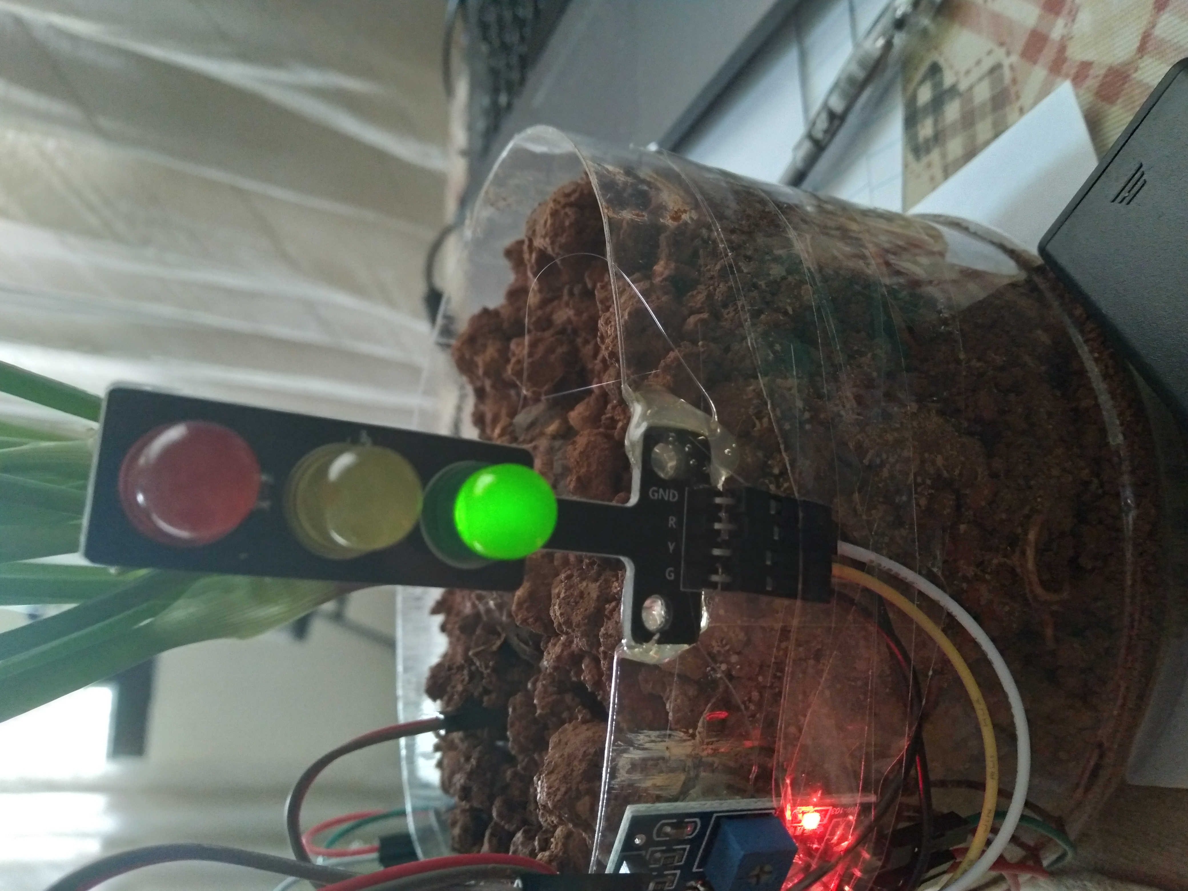
Connectivity indicator
To make use of the LED traffic light from the farming kit, I am going to use it as connectivity indicator.
MQTT server down
If the MQTT server is down, red and orange led will turn on.
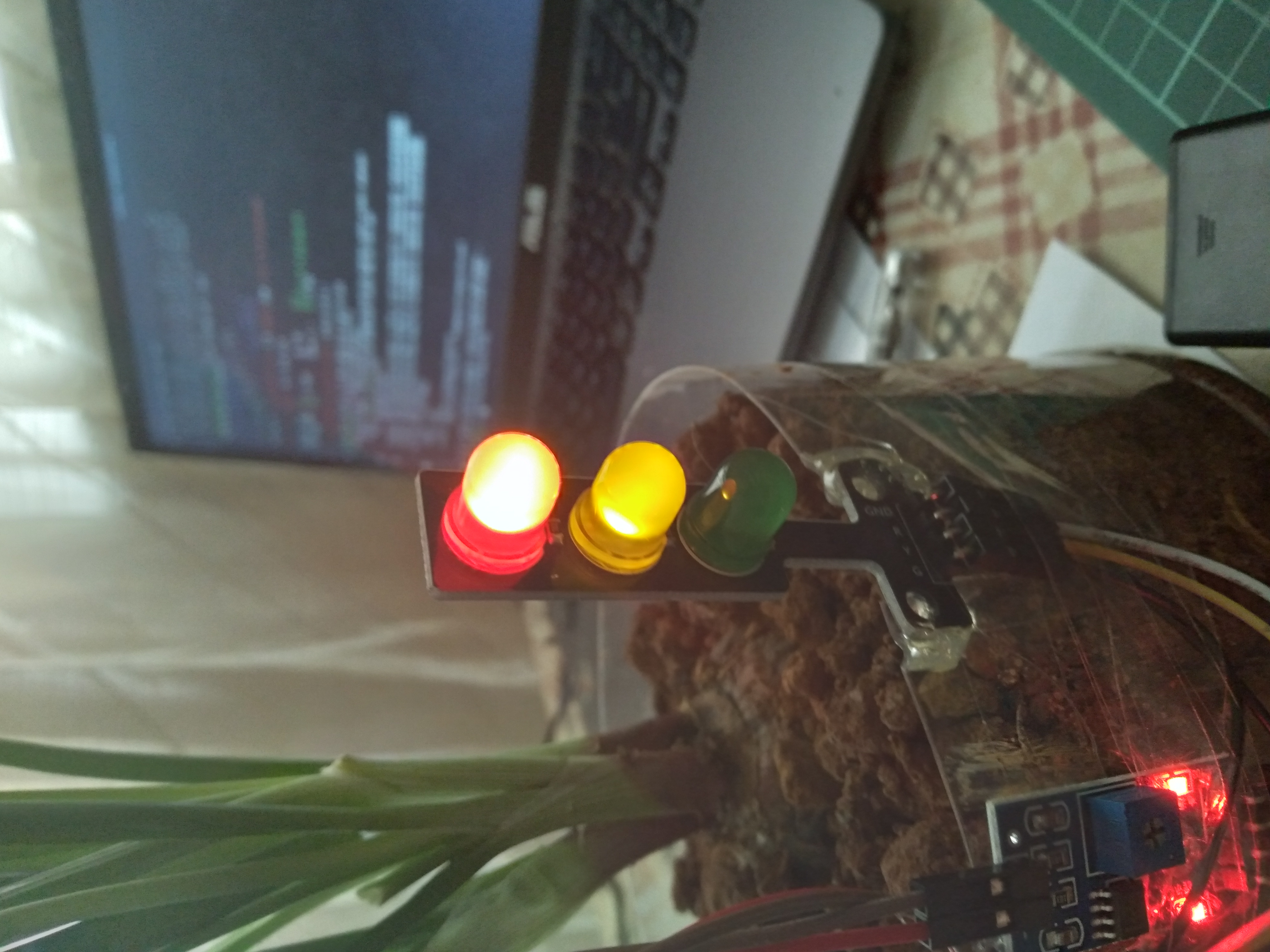
Node Red server down
If the Node Red server is down, green and orange led will turn on.
Everything in good status
If both servers is online, green led will turn on.
Power consumption test
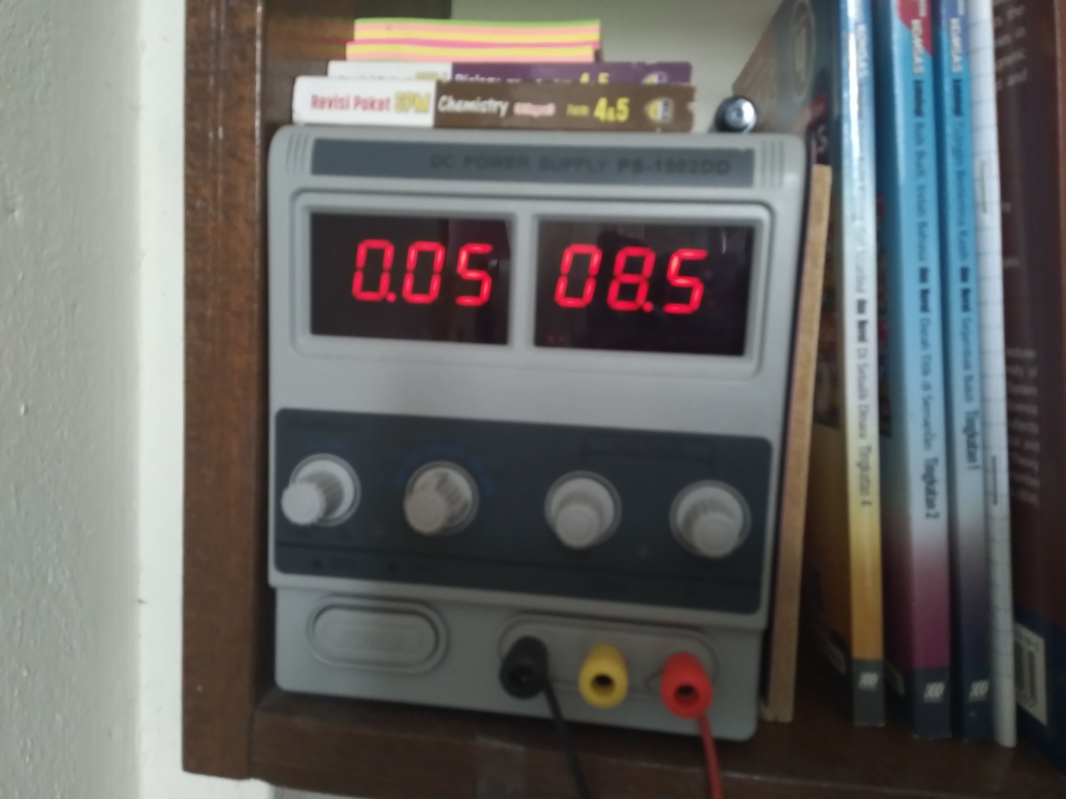
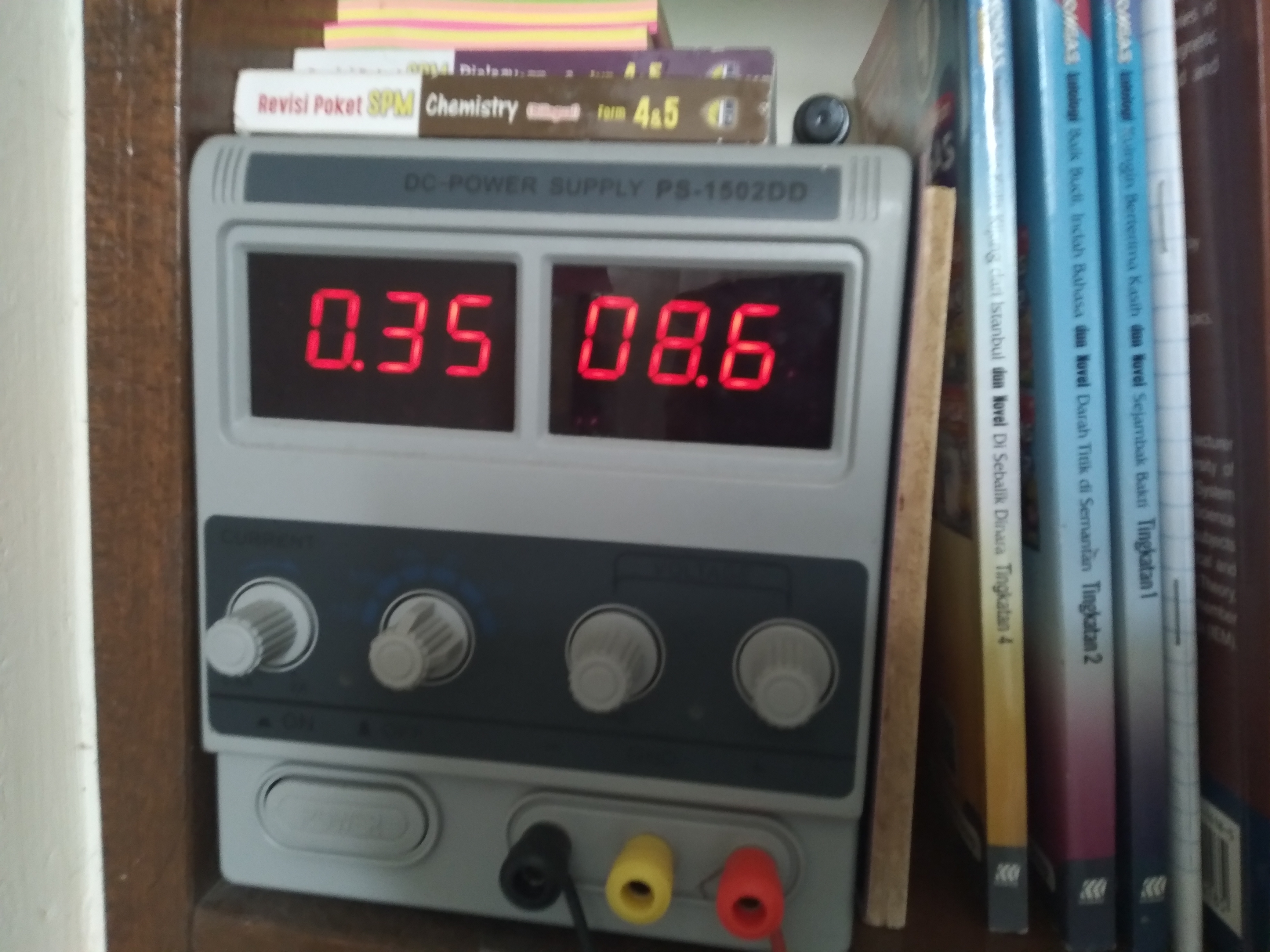
Because this IoT farm is going to use for a long time, understand its power consumption is important so the battery wont run out so often. To test the power consumption, I use a lab bench power supply which has ammeter and set its output voltage to around 8.5V. (The voltmeter of the power supply has zero error so 9V might burn the circuit.)
normal condition (water pump off)
running condition (water pump on but no load)
on-load condition (water pump on and pumping water)
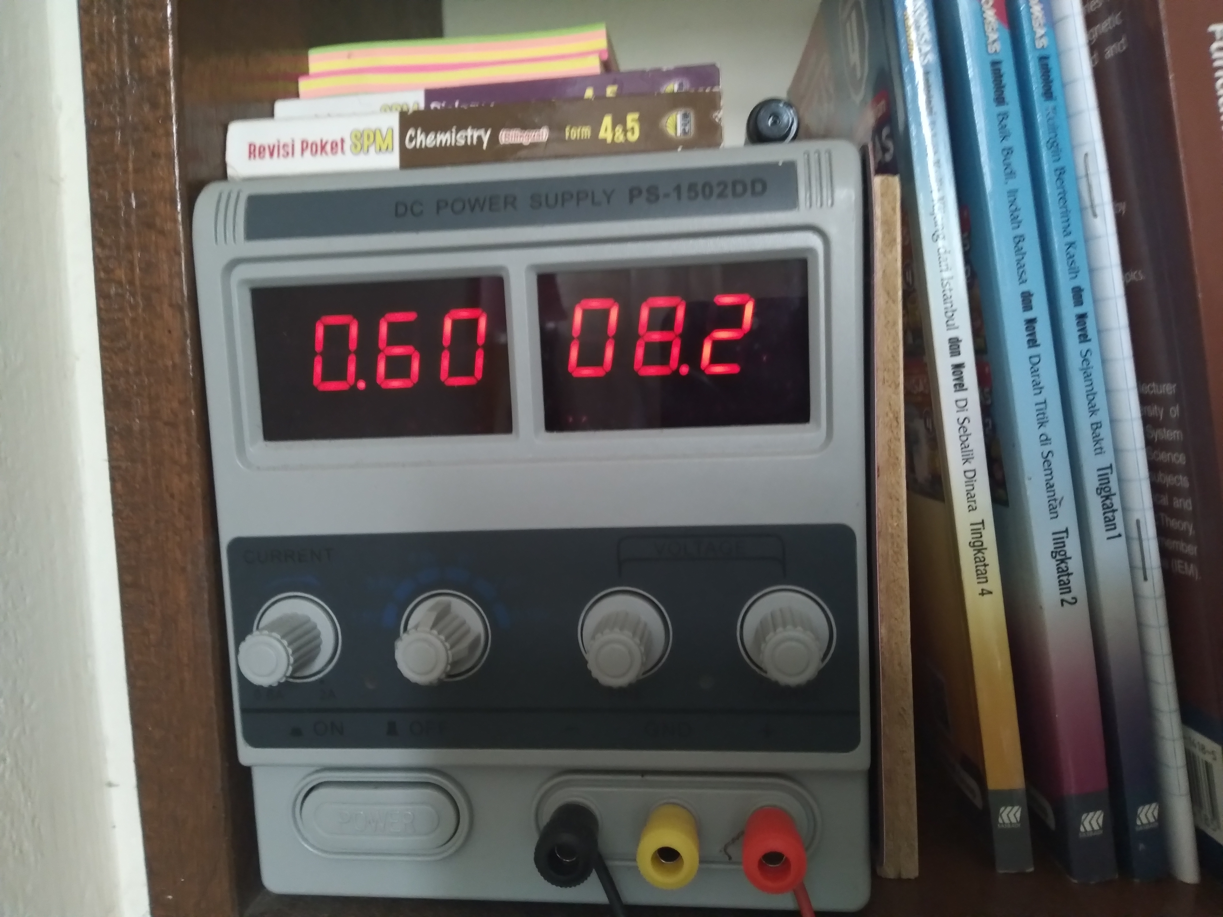
So, here is the result:
| Condition | Voltage | Ampere | Power |
|---|---|---|---|
| idle | 8.5V | 0.05A | 0.425W |
| no load | 8.6V | 0.35A | 3.01W |
| on load | 8.2V | 0.6A | 4.92W |
The power consumption in idle condition is quite high if it is only power by non-rechargable battery. So, I will replace the power supply to solar panel in the future.
Mechanism behind it
Connection diagram
As a summary, here is the connection diagram between each device.
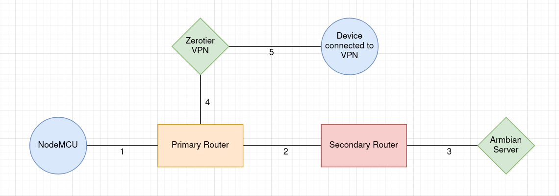
- Wifi connection between primary router and NodeMCU.
- connection between primary router and secondary router sparated into two LAN.
- connection between secondary router and Armbian server with Internet access.
- Armbian server connected to p2p vpn through both router.
- Outer device can route through p2p vpn and able to access secondary router LAN via armbian server ip forwarding.
MQTT
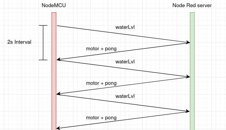
Meanwhile, the MQTT part is quite simple, only three event involved.
- waterLvl - Indicate moisture in soil, the higher the value, the less moist the soil.
- motor - Control pump. If value is 0, then turn on the pump, vice versa.
- pong - Used to indicate whether Node Red server is working. (actually can use motor event to indicate)
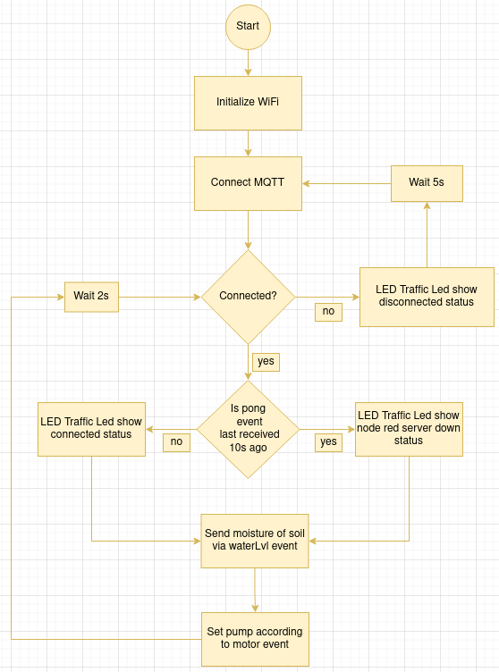
Flowchart
I only do the flowchart for the NodeMCU side because Node Red is already use graphical programming to program.
Code
1 | |