Atmega328p PWM control using register
PWM as known as pulse width modulation is a necessary feature in microcontroller nowaday. With the function of PWM, a digital pin on a microcontroller which can toggle on and off can be used as analog pin by toggling the pin at a very high frequency and specific on and off period. PWM also has wide application in robotics field such as control speed of DC motor and brightness of light bulb without adding complicated electronic circuit. However, only know how to use PWM is not enough, study the principle behind it can give us a better idea about how it works.
Nowadays, Atmega328p is commonly used in Arduino UNO and it has 6 PWM pin. Each 2 of the pins are attach to internal timer. This means that PWM operation can be done completely using register.
The mechanism behind it
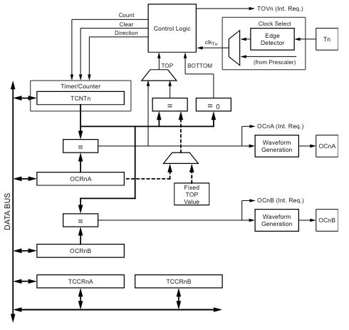
A block diagram of 8-bit timer from Atmega328p datasheet

Type of PWM mode
There are three types of PWM operation mode can be done by Atmega328p
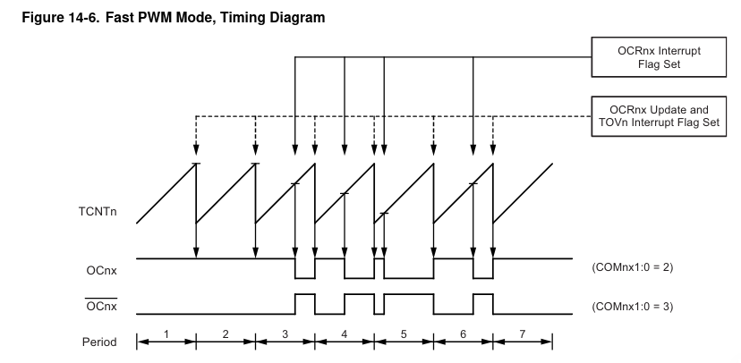
Fast PWM mode
When the counter reachs the top value, the value in counter clear. The waveform is sawtooth
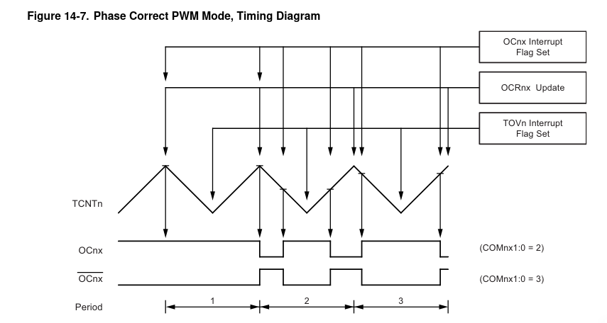
Phase correct mode
When the counter reachs the top value, the value in counter decrease. The waveform is triangle.
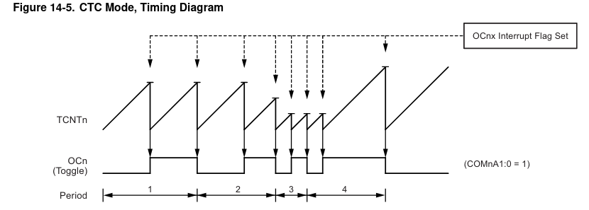
CTC mode
CTC mode is non commonly used and it can control the PWM better.The waveform is sawtooth.
Description of each timer and its register
The description is too long so I am not going to add this into this blog. Otherwise, this blog is going to become too long.
You can get the description from the offical documentation page 74
How to use these registers in code
Well, here is the procedure needed to set PWM properly.
- Toggle PWM pin to OUTPUT mode using DDRX (Data Direction Register)
- Set the compare mode of PWM using TCCRX (Timer/counter Control Register)
- (Timer 1 only) Set top value to ICR (Input Capture Register)
- Set the duty cycle value into the OCRX (Output Compare Register)
If you want to disable the PWM of a pin, here is the procedure.
- Set the compare mode of PWM to disabled which is 0 using TCCRX (Timer/counter Control Register)
- (Optional) Clear the duty cycle value into the OCRX (Output Compare Register)
Coding part
After learning some basic knowledge of PWM, let’s write some code. :)
1 | |